Where the GDH-CE Ducted Series Fits Best
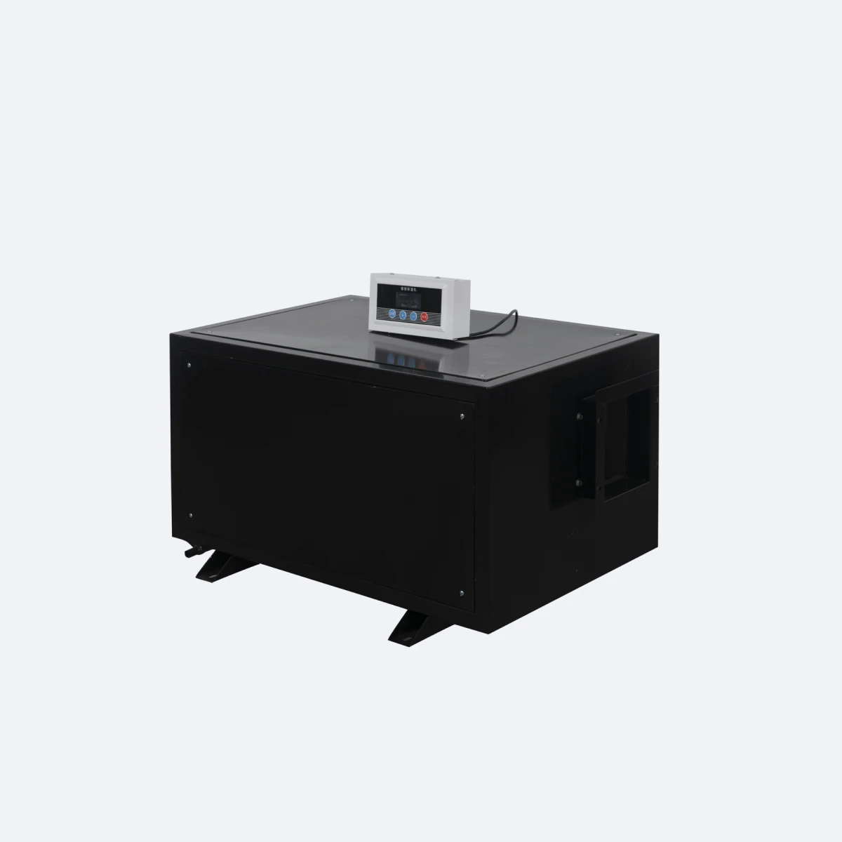
The GDH-CE ducted dehumidifier series is sized for commercial HVAC-integrated installations where moisture treatment is part of the building's broader air handling strategy. Typical applications: hotel guest floor wings with shared HVAC infrastructure, large office floors with zoned humidity requirements, indoor pool plant rooms with significant evaporation load, healthcare facilities with strict humidity control needs, archive and document storage facilities, food processing facilities, and large grow-room operations with high transpiration loads.
The series installs in mechanical rooms, plant rooms, or oversized ceiling voids capable of accommodating the 800 × 540 × 470 mm cabinet (or 950 × 600 × 700 mm for the CE168). Air distribution to the conditioned spaces happens through standard HVAC ductwork connected to the unit's intake and discharge ports. This is not a portable equipment class — the 49–70 kg weight, ducted-only air distribution, plumbed-only drainage, and lack of internal water tank all signal a fixed-installation unit.
Why Four Capacity Tiers — Sizing to Zone Load
The four-tier capacity structure (90, 138, 156, 168 L/day) is the design choice that separates this series from competitor lines covering the same range with two or three model points. Four tiers narrow the maximum oversizing ratio to about 30 %, which matters for energy efficiency and part-load behavior across multi-zone commercial projects:
- CE90 (80–120 m²) — small commercial zones, single conference rooms, small archive halls, hotel suite groups
- CE138 (120–140 m²) — mid-sized zones, larger archive rooms, mid-sized retail areas, small server rooms
- CE156 (140–160 m²) — large single zones, full hotel guest floor wings, mid-sized commercial floors
- CE168 (160–220 m²) — large open zones, manufacturing process areas, large server rooms, indoor pool plant rooms
For mixed-load buildings (a floor with rooms of different sizes and humidity loads), the practical approach is to install different tier units in each zone rather than one oversized central unit. This is the central vs distributed dehumidification decision — distributed wins on flexibility, part-load efficiency and redundancy, at the cost of a higher install count. The four-tier capacity structure makes the distributed approach economically practical because the right unit exists for each zone load.
Ductwork Integration — Static Pressure and Airflow Targets
The CE90, CE138 and CE156 each deliver 1200 m³/h air circulation (roughly 705 CFM). The CE168 delivers 2200 m³/h (roughly 1295 CFM). External static pressure rating is up to 100 Pa for the 1200 m³/h models and 150 Pa for the CE168 — enough headroom for typical commercial ductwork runs with reasonable filter and grille restrictions.
For duct sizing, target a main supply velocity of 4–5 m/s in low-noise commercial installations or 5–7 m/s in industrial environments where ductwork noise is less critical. Standard installation includes a G4 particulate filter on the return side (F7 if local air quality requires it) and a balancing damper on each supply branch for zone-level airflow tuning. The unit's intake and discharge ports are circular with flanged connections sized to fit standard HVAC ducting accessories — no proprietary fittings required.
Dual Copper Coil with Titanium Foil Fins
The heat exchanger uses dual oxygen-free copper coils — separate evaporator and condenser circuits — with titanium foil treatment applied to the fin surfaces. The dual-coil arrangement increases active heat exchange surface per unit volume, allowing the cabinet footprint to stay manageable while delivering the rated extraction at the rated airflow.
Titanium foil fin treatment provides corrosion resistance well beyond hydrophilic aluminum coatings used on standard portable dehumidifier coils. For ducted installations running continuously across multi-year service cycles in damp ambient air, this extends coil service life from the 5–7 years typical of hydrophilic aluminum coils to 10–12 years, closer to the typical building-systems replacement interval.
R32 Refrigerant — Standard Charge, Regulated-Market Compliance
All four models use R32 refrigerant (HFC single-component, GWP 675, A2L mildly flammable) with factory-sealed circuits as the standard configuration. R32 is the established compliance choice across regulated global markets — EU under the revised F-gas Regulation (EU 2024/573), UK, Japan under the Fluorocarbons Emissions Control Law, Australia, and increasingly across North America, China, and other markets phasing out legacy HFC blends. Single-component composition eliminates the fractionation risk associated with blended refrigerants during charge and top-up service — a meaningful maintenance advantage for precision equipment operating on multi-year service cycles in mission-critical cleanroom, pharmaceutical, and data center installations. R32 charge volumes are compact — below the IEC 60335-2-40 charge limits for the installation category, with exact charge specified per model in the technical documentation package provided at order. For facility safety policies that require additional ventilation analysis for A2L refrigerant in confined cleanroom or laboratory installations, we provide the charge and ventilation reference data required for the assessment.
Direct Hose Drainage
All four models drain condensate by direct hose connection to a building drain endpoint. There is no internal water tank — these are continuous-operation fixed installations where tank emptying makes no sense at 90+ L/day extraction. The drain port is G3/4" threaded on the rear cabinet.
Standard installation routes the drain hose to a floor drain, mop sink or HVAC condensate manifold within 3–5 meters of the unit, with continuous downward slope at 1–2 % gradient. For installations where the drain endpoint sits above the unit (typical for ceiling-void installations), an external condensate pump is required between the unit and the drain. The units have no built-in pump; for ceiling-void installations a small condensate pump in the ceiling void rated 100–200 L/h lifts condensate to a higher drain endpoint.
Operating Temperature — Why the Range Narrows With Capacity
Working temperature ranges narrow as rated capacity climbs across the series:
- CE90: 5–38 °C
- CE138: 5–35 °C
- CE156 and CE168: 5–30 °C
This pattern follows the same physics across our larger refrigerant-cycle units. Higher rated power means more internal heat generation during operation, which limits the safe upper ambient temperature for the internal electronics and sensor PCB. Industrial and commercial spaces operating at 18–28 °C are comfortably inside the envelope for all four models. Hot manufacturing or process spaces above 30 °C ambient should specify the CE90 (highest upper limit) or accept the operational constraints of the larger units. For sustained operation below 5 °C, switch to a desiccant-type rotary dehumidifier — the working principle is adsorption rather than condensation and effective extraction continues down past –20 °C.
BMS Integration and Multi-Unit Coordination
For projects with multiple units distributed across zones, BMS integration via Modbus RTU output is available as an ODM option from MOQ 50 units. The Modbus interface provides read access to current RH, target RH, operating mode, fault codes and runtime hours, plus write access to setpoint and operating mode. For projects without full BMS infrastructure, dry-contact alarm outputs (fault relay, runtime relay) provide a simpler integration path with standard building automation panels.
For larger systems requiring BACnet IP, KNX or OPC UA integration, quote per project — the control board hardware supports add-on modules, but specifying the integration during ODM avoids the cost of field retrofits after installation.
Build and Safety
1.0 mm cold-rolled steel housing with electrostatic powder coating in standard black finish for mechanical-room visibility. Internal electrical components receive moisture-proof conformal coating before assembly. Each unit is leakage-tested at full extraction conditions before shipping — the leakage-free design point matters for ducted installations where any water leak would damage ductwork and surrounding ceiling or floor. Built-in safety: high-pressure cut-out, overcurrent protection, defrost interlock, fault self-protection logic and compressor thermal cut-out.
OEM and ODM Service
OEM MOQ is 10 units per model — branding, cabinet color (standard black; any RAL or Pantone for installation-visible surfaces), power cord and plug type for the destination market, packaging artwork. For installation-channel buyers, common OEM specifications include extended power cord length, factory-bundled condensate pump and drain hose kit, dedicated mounting brackets or anti-vibration pads, and pre-fitted return-air filters. ODM scope covers BMS integration (Modbus RTU from MOQ 50, BACnet/KNX from MOQ 200), alternative refrigerant (R32 from MOQ 200), structural modifications, and certification routing (CE, RoHS, ETL, SAA, GS depending on target market). Production lead time is 30–40 days after artwork sign-off — slightly longer than smaller units due to per-model batching across the four capacity tiers. FOB Ningbo or Shanghai.
For the slim-profile single-zone option, see the ceiling mounted dehumidifier (CE38, 220 mm cabinet). For other tiers in our full commercial dehumidifier range, browse the category page.